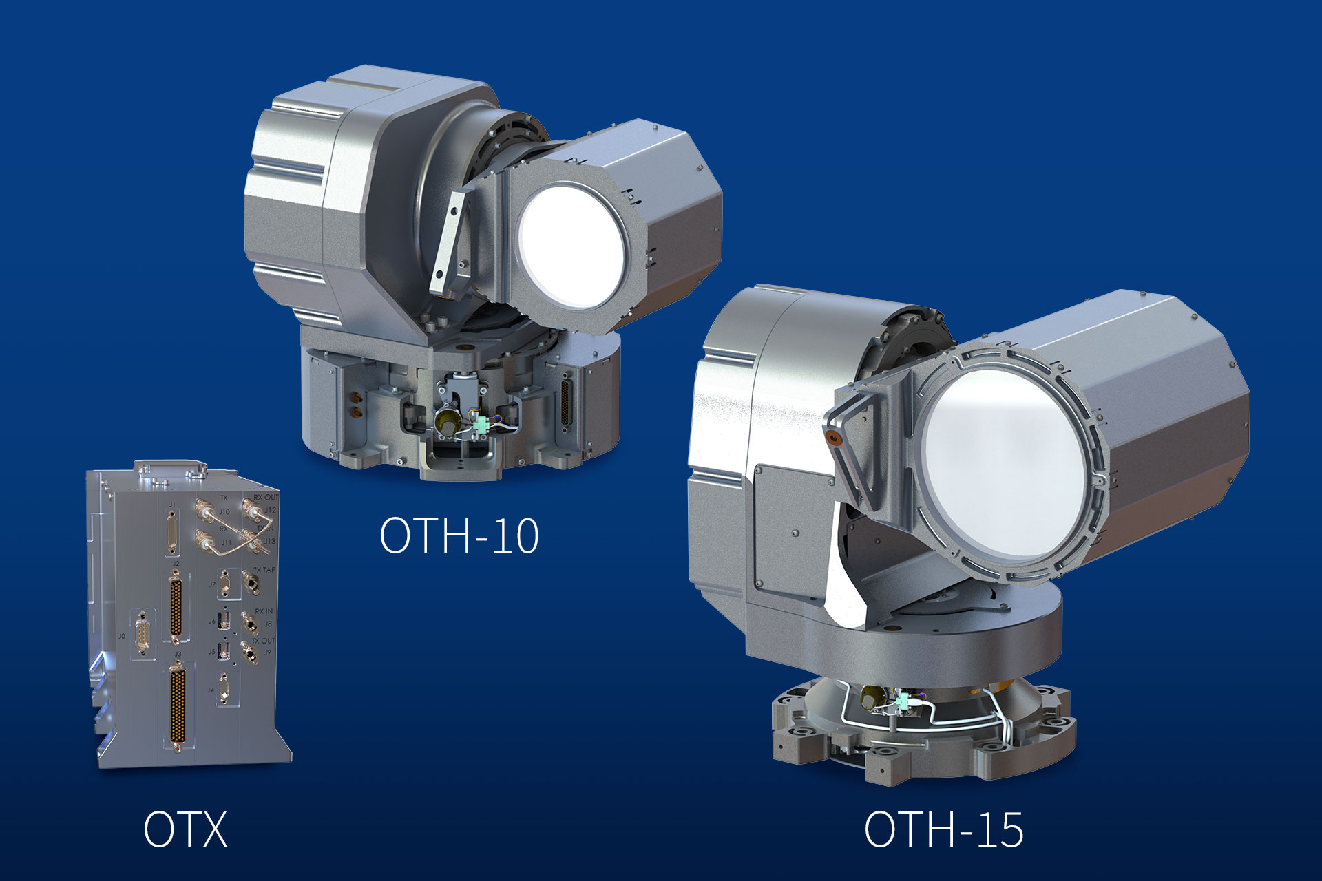
BMOT Optical Terminal
Blue Marble Communications Optical Terminal (BMOT) is the highest performance optical communication terminal solution available on the market, featuring:
- Industry-leading combination of optical aperture and transmit power, enabling high data rates at long link ranges,
- Two dual-waveform optical modem options:
- 10G NRZ OOK & Burst-Mode OOK (SDA OCT v3.2 & v4.0) waveforms, or
- 100G DP-QPSK (Open ZR+, ESTOL) & 10G NRZ OOK (SDA OCT v3.2) waveforms,
- Packet erasure coding for atmospheric turbulence fading mitigation in bidirectional space-to-ground links,
- Industry-leading power efficiency and radiation performance with all 7nm FPGA/ASIC processing,
- Reliability & radiation hardness assurance for harsh 10+ year MEO & GEO missions.
BMOT integrates seamlessly with BMC’s network routing, edge computing, and RF waveform processing products to provide a single integrated mission payload solution for spaceborne communications & computing systems.
Technical specifications
| Parameter | Performance |
| Configuration |
BMOT-10 = OTX + OTH-10 (10cm) BMOT-15 = OTX + OTH-15 (15cm) |
| Data Rate & Waveform |
1-10Gbps SP-OOK 100Gbps DP-QPSK |
| Transmit Power | 10W (power amplifier output) |
| Link Range Performance |
100Gbps : 30,000km (15↔15), 15,000km (10↔10) 2Gbps : 20,000km (10↔10), 30,000km (10↔15) |
| Field of Regard | 330° Azimuth, 220° Elevation |
| Angular Velocity | 5.0°/sec, 2.5°/sec² |
| Range Rate Tolerance | ±15.0km/sec |
| Wavelength Tunability |
1536.61–1542.94nm (ITU C43–C51) 1553.33–1563.05nm (ITU C18–C30) |
| Acquisition Time |
<100sec (BMOT-15 with ±1.0mrad attitude error) <100sec (BMOT-10 with ±1.5mrad attitude error) |
| Data Interfaces | 2x 100GBASE-KR4, 1x 2.5G/5G/10GBASE-T |
| Timing Interfaces | 1PPS LVDS, 10MHz LVDS |
| Monitor & Control Interface | 10/100/1000BASE-T, RS-422, CAN |
| Mass & Size |
OTX : 6.7kg , 27×14×20cm OTH-10 : 15.2kg, Ø42×29cm (stowed), Ø50×32cm (swept) OTH-15 : 24.9kg, Ø48×45cm (stowed), Ø59×50cm (swept) |
| DC Power (TX Power) | 130W (10W), 100W (5W), 80W (2.5W) |
| Operating Temperature | -10 to +60°C |
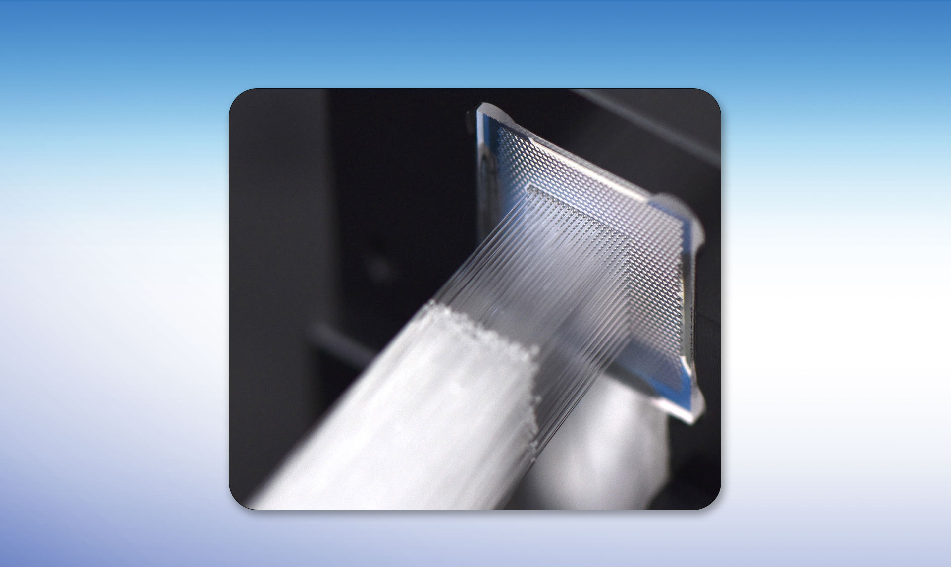
Medusa™ Fiber µlens Array
High-density, laser-welded, fiber-optic arrays for precision and robustness
Medusa™ fiberized microlens arrays offer nearly limitless scaling for fiber interconnects that cannot be matched by competing technologies. Laser-welded fibers ensure robust adhesion and 100% fused silica beam path, while automated alignment guarantees performance specifications regardless of fiber type.
Dense-packing with configurable placement
Medusa™ fiberized microlens arrays can be pre-configured to provide any fiber density any location for any type of fiber, including mixed fiber types. Epoxy-free path provides uninterrupted silica path for high reliability applications such as datacenter interconnects, silicon photonics interconnects, or kW-per-fiber beam combination.
Technical specifications
The preliminary specifications of Medusa™ fiberized microlens arrays are given below:
- Fiber type: SM, PM, MM, LMA, or mixed
- Number of fibers: 128, or user defined to over 1024
- Fiber configuration: hex-pack, square pack, or user defined
- Center-to-center spacing: user defined ≤ 250µm
- Pointing error: ≤ 2.5mrad
- PM fiber co-alignment: ≤0.3°
- Connector loss per channel: 0.5/1.6dB (avg/max)
Manufacturing features of Medusa™ fiberized microlens arrays make them suitable for integration into high-density expanded-beam connectors. Such features include:
- Bar-coded fibers for easy correlation to microlens location
- Mounted or unmounted microlens array
- Epoxy filled (not in path) for hermetic strain-relief